

The landing begins with the traffic circuit

A safe landing is neither a controlled crash nor something you need to be afraid of. The landing itself begins long before the flare at the runway threshold. If you follow the principle of “stabilized approach criteria” and keep airspeed, descent rate, glide path, and configuration within clearly defined limits, your first successful landings won’t be far away. What helps professionals also gives you a structured way to manage the approach.
Through pitch control (elevator), you primarily control airspeed throughout the approach, while engine power mainly controls the descent rate and thus the glide path. Ailerons and rudder ensure a coordinated flight attitude. The landing is essentially “distributed” over the traffic curcuit, giving you time for corrections and providing a structured framework that brings you safely to the runway threshold.
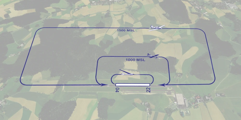
The traffic circuit brings structure to the landing
The traffic circuit is not a meaningless ritual, but a safety concept. Through a standard sequence of downwind, base, and final leg, it creates a structured framework that you can rely on and that allows you to land more safely even at unfamiliar airfields. On the downwind leg, you first check airspeed and altitude and plan the start of your descent. In principle, this is where the landing begins.
On the base leg, you will already start descending at many airfields and configure the aircraft for landing. Power is reduced, the first stage of flaps is extended, and a safe approach speed is maintained. The goal is to be neither too high nor too fast when turning onto final approach.
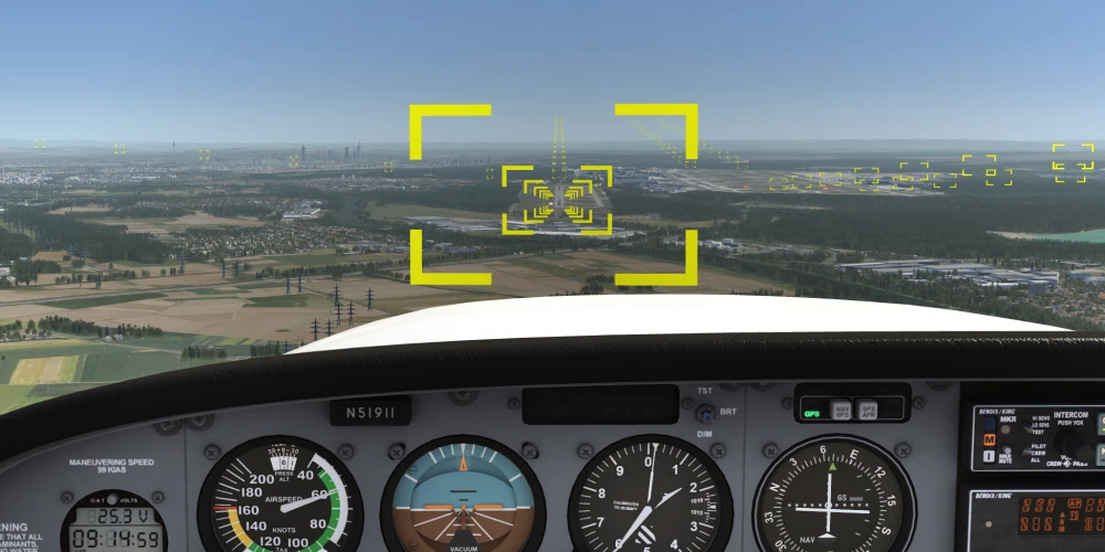
On final approach, you align the aircraft precisely with the runway. At this stage, precise and sensitive control is essential. You stabilise the approach speed and maintain a constant glide path that carries you safely to the runway threshold. The airspeed indicator, vertical speed indicator, and altimeter are your most important aids in this phase.
However, they only complement your visual perception of the aiming point markings, runway edges, and the horizon. These visual cues also provide crucial information about glide path and aircraft attitude. Even though modern cockpits offer many instruments, the approach in visual flight remains primarily a visual manoeuvre.
A good landing results from the combination of looking ahead and monitoring the instruments. It is also important to internalise that you do not control altitude in the approach with the elevator, but rather airspeed. The glide path is therefore not “stretched” with the elevator, but maintained by adjusting engine power. Just before the threshold, power is reduced further and the flare is initiated. By gently pulling back, you increase the angle of attack. The descent rate decreases, airspeed continues to reduce, and the main landing gear touches down first.
Aerodynamically, you are gradually approaching the stall during the flare. At touchdown speed, the lift is just sufficient to keep the aircraft airborne. The goal is a smooth, controlled transition from flight to ground contact—without bouncing or dropping.
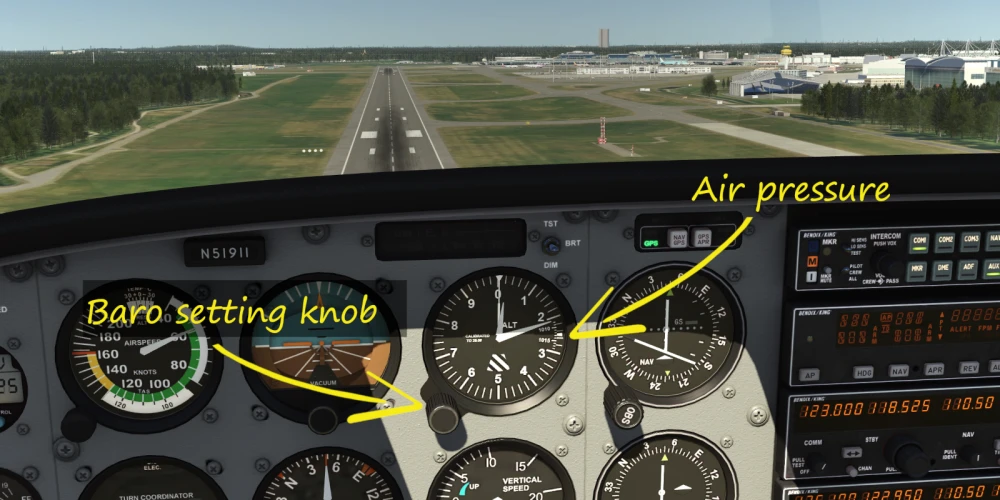
After practice, a bit of theory.
A visual flight rules (VFR) chart of your airfield provides all the information you need for a correct circuit setup: aerodrome elevation, published traffic curcuit altitude, runway orientation, circuit direction, and any special procedures. On the chart, the aerodrome elevation is given in feet above MSL (mean sea level). This value is important because it is the basis for determining your traffic circuit altitude.
If a traffic circuit altitude of 1000 ft AGL (above ground level) is published and the aerodrome elevation is 1200 ft MSL (mean sea level), then the resulting traffic circuit altitude is 2,200 ft MSL (mean sea level).
With the correct QNH set (barometric pressure referenced to mean sea level), your altimeter indicates altitude above MSL (mean sea level). However, traffic curcuit altitudes are often published in AGL (above ground level), which makes conversion necessary. The runway orientation information is also clearly defined: the runway number (RWY – runway, takeoff and landing strip) corresponds to the magnetic heading of the runway, rounded to the nearest ten degrees.
A runway 22 therefore indicates an orientation of approximately 220°. If you learn to correctly interpret this chart, you will not simply approach the runway “somehow,” but instead integrate yourself in a controlled and structured manner into the existing traffic flow.