More about the instruments
If you want to learn more about the instruments of the Cessna, you can find a detailed description of the cockpit and its controls under aircraft tutorials.


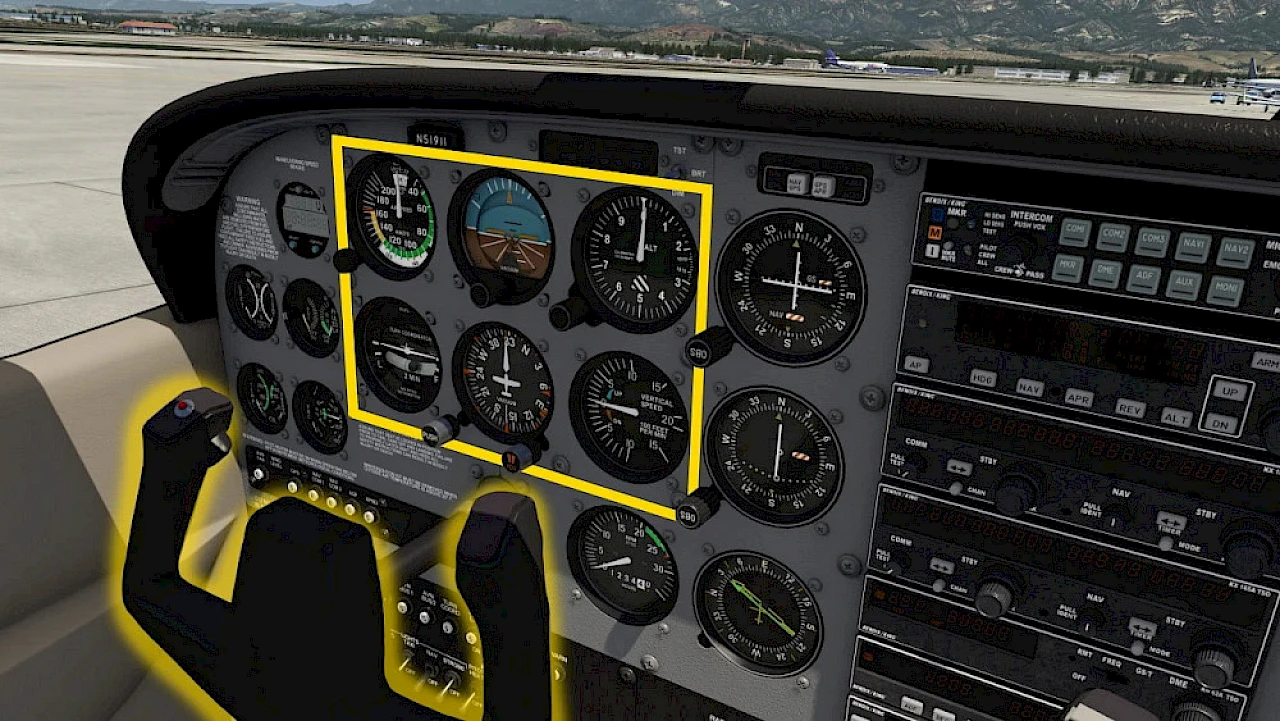
Looking at the main instrument panel we find the classic six-pack of the most important flight instruments which we highlighted on the screenshot. In front of you you can find the control yoke which is used to steer the aircraft in the air. At your feet you can also find rudder pedals which are used to steer on the ground and to keep the nose pointing straight in the air.
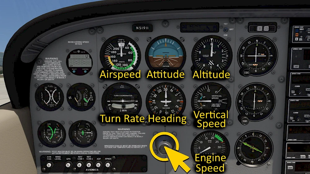
Let’s take a closer look at the most important instruments. Take your time to inspect the instruments up close. From the top left to bottom right these are:
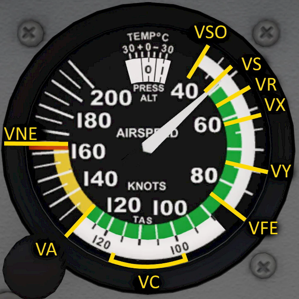
The airspeed indicator uses the pitot and static pressure from small openings in the fuselage and on the wing to mechanically compute the speed of the oncoming air. This is the indicated airspeed and is typically measured in knots, giving us a speed in KIAS, knots indicated airspeed. For the simple case of flying straight and level we can still give some good speed estimates for the airspeed at which the aircraft will stall.
The stall speed in landing configuration, referred to as VS1, is 40 KIAS and corresponds to the beginning of the white arc on the airspeed indicator. In contrast, the stall speed in clean configuration, VS0, is 48 KIAS and marks the beginning of the green arc. The rotation speed (VR), at which the aircraft begins to lift off during takeoff, is 55 KIAS and is not specifically marked on the airspeed indicator.
For climb performance, the best angle-of-climb speed (VX) is 62 KIAS, while the best rate-of-climb speed (VY) is 74 KIAS; neither of these speeds is marked on the indicator. The maximum flap extended speed (VFE) depends on flap position: up to 10 degrees, it is 110 KIAS, while for more than 10 degrees, it is limited to 85 KIAS. The white arc on the airspeed indicator ends at 85 KIAS, indicating the upper limit for safe flap operation.
The typical cruising speed (VC) ranges between 90 and 120 KIAS and is also not marked. The maneuvering speed (VA), which allows for abrupt control inputs without overstressing the aircraft, is 105 KIAS. The maximum structural cruising speed (VNO) is 129 KIAS and is indicated by the beginning of the yellow arc. Finally, the never-exceed speed (VNE) is 163 KIAS and is marked by the red line on the airspeed indicator.
The attitude indicator consists of three gyroscopes that maintain their attitude relative to the ground reference. The gyros remain in a fixed attitude while the aircraft rotates around it. Attached to them is a symbolic picture with a white horizontal line to represent the horizon, a blue sky part above and a brown earth color for the ground. You can also see several lines marking the pitch angles and bank angles to be able to read these angles in degrees.
Thin white horizontal lines mark the pitch angles -5°, -10° and -15° and thin horizontal black lines mark the pitch angles +5° and +10°.
White diagonal lines at the on the brown earth part show the 22.5° and 45° bank angles. The white dashes at the top of the instrument indicate the bank angles 0°, 10°, 20°, 30°, 60° and 90° for left and right turns.
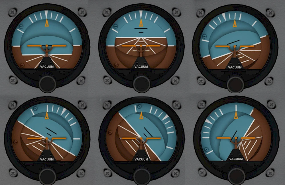
The image on the right shows the the following situations in flight.
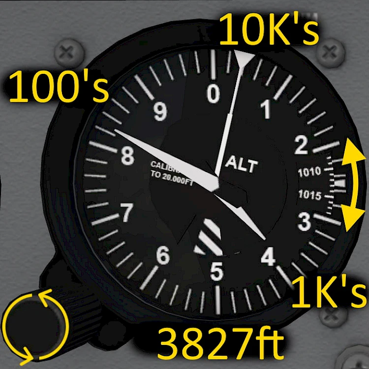
The altimeter is a diagram that expands and retracts as the ambient air pressure changes. It compares the pressure difference of the currently measured air pressure to a reference pressure set with an adjustment knob. The altimeter doesn’t show the altitude above sea level or above ground correctly unless it is calibrated to the current air pressure on the ground or sea level.
The correct pressure setting is given by local weather stations, automatic terminal information service (ATIS) or automated weather observing system (AWOS). In standard conditions the pressure is 1013 hPa or 29.29 inches of mercury (inHg).
The altimeter indicates the pressure difference between the set ground pressure or sea level pressure to the currently measured static air pressure. It shows the derived altitude with three needles.
The longest and thinnest needle with the triangle at the end shows the altitude in ten thousand feet increments.
The short and thick needle shows altitude in 1000 feet increments.
The long and thick needle shows increments in 100 feet.
To read the altitude correctly you have to combine these three needle indications in your head. First you read the 10k needle. In our example it shows roughly 0.4 something which is well below the ‘1’ on the scale, so we know we’re roughly at 4000ft but well below 10,000 ft and we can ignore the 10k needle in our calculation. Then we read the second needle, which in our example indicates 3.8 something. So we know we’re somewhere close to 3800ft. Lastly we read the third needle which shows 8.2 something so 820ft.
Combine all three needles: 0 x 10000ft + 3000ft + 820ft = 3820ft
The turn indicator consists of an airplane symbol and a balance ball suspended in water or other fluid types.
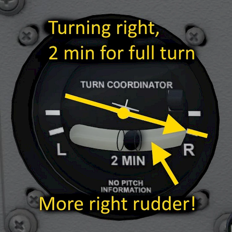
When the airplane wings are horizontal then the airplane is not turning at all. When the left wing tip tips down to the white marker then you are flying a turn to the left at standard rate which completes a full 360° turn in two minutes. A 180° turn will take 60 seconds and a 90° turn takes 30 seconds at that turn rate.
These standard rate turns (2 minutes for a full circle) are used in instrument flying conditions to fly standard procedure turns which can be flown relatively precisely even with this one basic instrument.
Internally the turn indicator is another gyroscope that it allowed to tilt depending on the change in heading. As the nose of the airplane yaws left and right the turn indicator shows the rate of turn of the fuselage as seen from above.
The turn indicator does not shot the bank angle of the plane and it also does not show any pitch information. These can be found on the instrument directly above it, the attitude indicator.
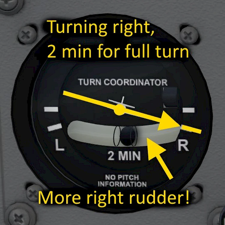
The second and lower part of the instrument is the balance ball. This acts just like a balance scale but the tube is slightly curved upwards to the end to make it less sensitive. The ball inside the tube will be pulled down by the acceleration of the airplane and rolls to the lowest point. When we always point our nose straight into the wind the ball will be centered even if we fly turns. It is the equivalent of the forces that you feel when you sit in the airplane yourself.
When the airplane nose is not pointing straight into the wind the fuselage and vertical stabilizer as well as the propeller all will create a side forces. Sitting in the plane we can feel that we are pushed to left and right. The balance ball then also deflects left and right. To correct this we should apply rudder input to straighten out the airplane nose. Otherwise we generate extra drag and worsen the experience for passengers. Similarly in a small airplane you don’t want all of your passengers and luggage to be flung to one cabin side like they do in a car. Unlike a car the airplane is sensitive to being loaded asymmetrically and would start to roll slowly in an uncommanded fashion.
You can “kick the ball” back to neutral with your feet.
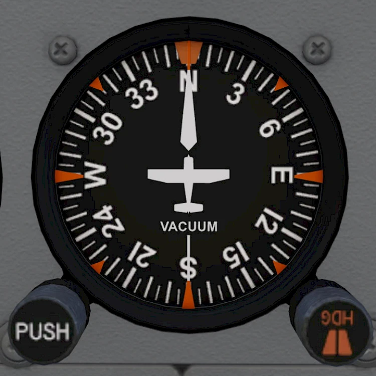
The heading indicator is a gyroscope that maintains its attitude even if the aircraft turns around it. You can think of the compass rose being stationary while the aircraft symbol turns with the actual airframe.
The heading indicator therefor shows the direction of the aircraft nose relative to the fix gyro reference. The gyro is adjusted to the known runway heading before taking off and during the flight it can also be re-calibrated using the magnetic compass on the windscreen. Aerofly FS manages this calibration for you and the heading indicator shows the correct magnetic heading for you.
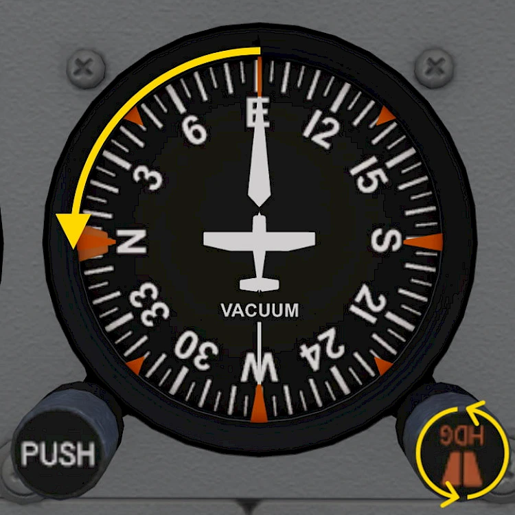
The heading indicator has a small heading bug that can be adjusted with the knob in the lower right corner
The vertical speed indicator shows the rate of climb and rate of descent by comparing the current air pressure with the pressure inside a pressure vessel. The air is allowed to flow in and out of this chamber and the needle moves according to that airflow.
With the needle at zero the aircraft is neither climbing nor descending. You are maintaining altitude for the moment.
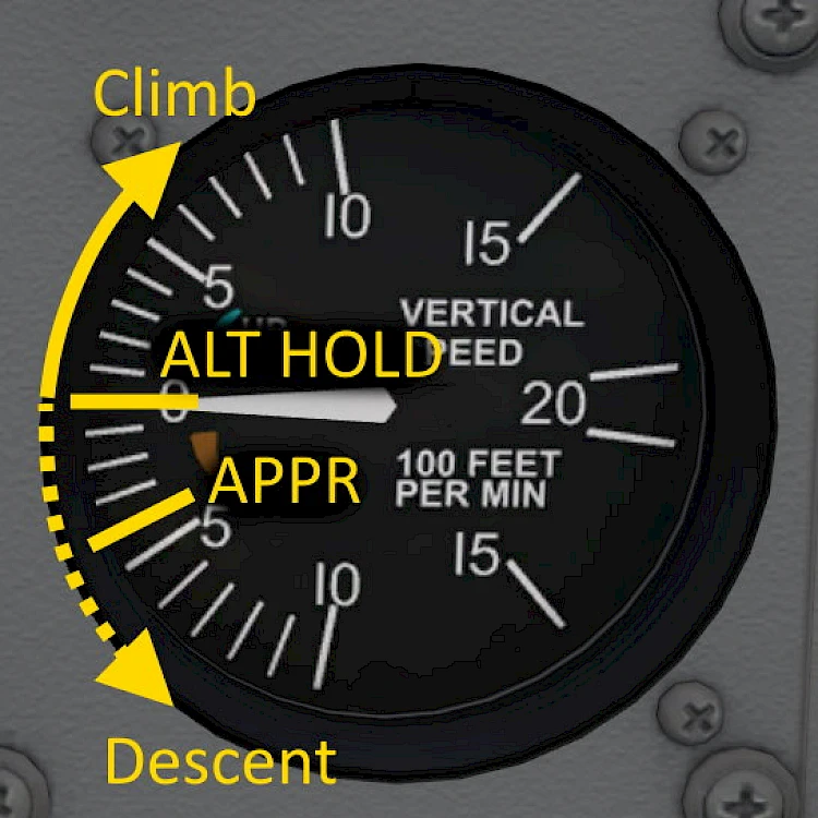
When the needle deflects up then you are climbing. It shows the rate of climb in 100 feet per minute. With the needle pointing at +10 for example you are climbing at 1,000 feet per minute. Climbing from 2,000 ft to 4000 ft will take two minutes at that rate.
If the needle is pointing down you are descending and loosing altitude. For approach and landing as a rule of thumb you can use your airspeed in knots and divide that by 2 to give you the necessary sink-rate indication for a stable 3° approach angle. For an approach speed of 70 knots in our Cessna this yields roughly 350 ft/min. For 80 kt it’s 400ft/min and for 100 kt it’s 500ft/min. The actual rate required depends on other factors like wind speed and actual ground speed but this is a good estimate.
This concludes the basic six most important instruments on the Cessna 172.